
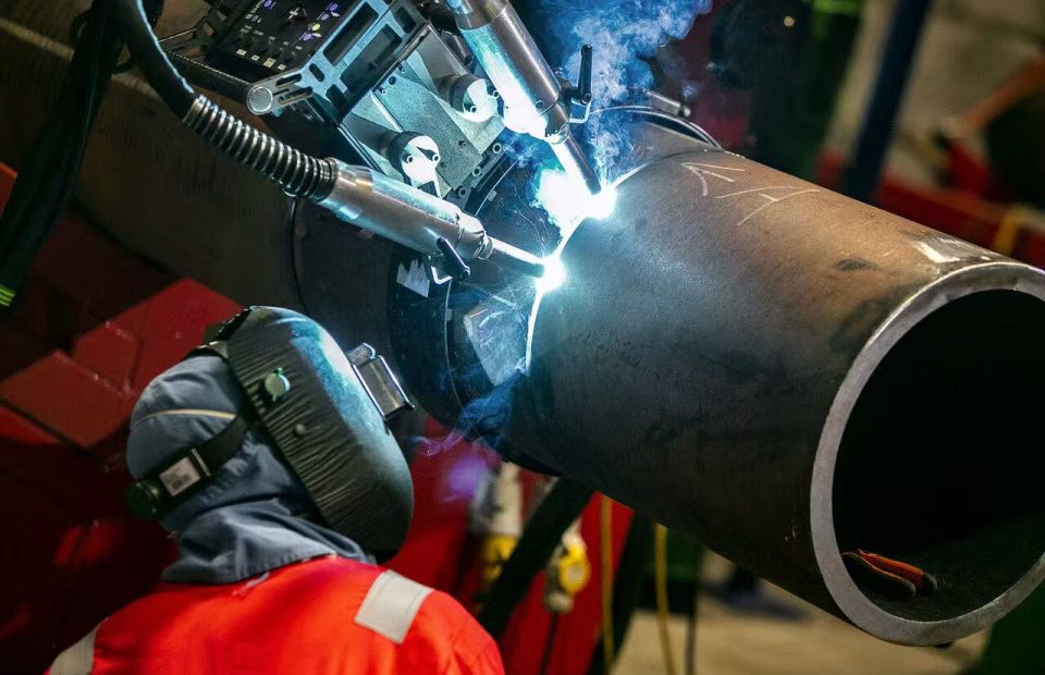
A clear comparison of welding cameras and laser seam po […]
A clear comparison of welding cameras and laser seam positioning sensors, including their outputs, control roles, interfaces and how they work together in automated welding cells.
Welding cameras and laser seam positioning sensors often get mentioned together, which leads to a common assumption: that they do the same job.
They don’t.
Both are optical. Both mount near the torch. Both matter in automated welding. But they answer two different questions, and confusing them is why some monitoring implementations underdeliver.
The One-Sentence Answer
A laser seam positioning sensor tells you where the joint is.
A welding camera shows you what the weld is doing.
One is a measurement device feeding a control loop. The other is an observation device feeding a person — or a customer-built AI layer.
How a Laser Seam Positioning Sensor Works
The operating chain has five stages:
1. Structured light projection. A laser line stripe is projected across the joint, ahead of the welding torch. The stripe deforms according to the joint’s cross-section.
2. Optical capture. A narrow band-pass filter and lens suppress arc light, spatter and fume glare. A CMOS imager captures the deformed stripe at high frame rate. Onboard processing extracts the stripe and identifies seam features — groove centre, edge, fillet, lap.
3. Seam coordinate output. The sensor outputs the seam position in its own frame (Xs / Ys / Zs) every cycle — the raw seam geometry that the control layer consumes.
4. Path computation. Host software handles teaching and scanning: set start and end points, scan the path, build the seam trajectory. A joint template library covers V, Y, butt, lap and fillet. Hand-eye calibration maps the sensor frame to the torch TCP frame, cancelling installation offsets. A deviation engine compares the found seam against the taught path and outputs ΔX / ΔY / ΔZ and angle θ.
5. Motion control. This is configured by the customer. Control programs vary between robot brands — KUKA KRL, FANUC TP, ABB RAPID, Yaskawa INFORM, ESTUN and others — so no universal motion program can be pre-loaded. The sensor delivers position data over Ethernet TCP/IP socket, PROFINET, EtherNet/IP, Modbus TCP or Modbus RTU over RS-485, with digital I/O handshake lines for hard-wired interlocking. Typical update is 10–20 ms.
The critical boundary: the sensor delivers position data — it does not drive the robot.
How a Welding Camera Works
Different device, different output.
A welding camera is built for weld monitoring in the arc zone. It does not measure seam geometry for path correction — it delivers visual observation and a frame-level record of what actually happened.
1. Camera hardware. Optics plus band-pass filter suppress arc light so the pool, seam and wire stay visible. A high-dynamic-range CMOS with global shutter and high frame rate handles arc welding conditions. Protection includes spatter shield, air purge and cooling for continuous duty. Mounting is on-torch bracket or off-axis fixture, coaxially aligned with the torch.
2. Basic software. Live view and recording with video and snapshot capture, camera parameter control (exposure, gain, ROI, trigger, frame rate), local archive for later review and traceability, session logs and multi-camera layouts.
An important scope limit: the base package observes and records only — it does not judge weld quality by itself.
3. SDK / API interface. Frame access API pulls every frame or receives it by callback, as raw or processed pixel data. Camera control API sets exposure, gain, ROI and trigger, and starts or stops recording programmatically. Language bindings cover C/C++, C# and Python with sample source code and API reference. Protocol options include RTSP, GigE Vision, shared memory or TCP socket. Metadata — timestamp, frame index, camera status and temperature — is output alongside each frame.
4. Customer AI layer. The customer builds datasets from their own welds, labels OK / defect cases, and calibrates pixel-to-mm and trains the model for their specific material, joint, gas and position. Two paths emerge:
- Path A — anomaly judgement. Detect porosity, spatter, undercut, burn-through, lack of fusion, arc instability.
- Path B — geometry extraction. Extract weld contour, seam position, bead width, pool and keyhole features.
5. Output and integration. Judgement output (OK / NOK with anomaly type, confidence and frame reference) and geometry output (contour points, seam width, offset as measurement data) feed shop-floor actions — alarm, HMI display, MES upload, quality records — according to the customer’s workflow. Optional closed loop: results can drive PLC or robot logic, pNXHY Launches New Arc Eye 3.0 Direct View Welding Camerarogrammed by the customer on their side.
Side-by-Side Comparison
| Dimension | Laser Seam Positioning Sensor | Welding Camera |
|---|---|---|
| Core question | Where is the joint? | What is the weld doing? |
| Observation point | Ahead of the torch | At the arc zone (coaxial) |
| Output | Coordinates: Xs/Ys/Zs, ΔX/ΔY/ΔZ, θ | Video frames + metadata |
| Primary role | Control loop input | Observation / evidence / AI input |
| Judges quality? | No — measures position | No — base package observes only |
| Who closes the loop | Customer’s motion program | Customer’s AI model (via SDK) |
| Typical update | 10–20 ms | Frame rate dependent |
| Interfaces | TCP/IP, PROFINET, EtherNet/IP, Modbus | GigE, USB3, RTSP, GigE Vision |
| Customer workload | Motion program per robot brand | Dataset, calibration, model training |
Why Automated Welding Increasingly Needs Both
What seam positioning guarantees
Robotic welding adoption keeps climbing, driven by the welder shortage and the demand for repeatability. Seam positioning is what makes that repeatability possible: it ensures the weld path follows the planned trajectory despite part variation, fit-up error and fixturing tolerance.
It answers: is the torch where it was supposed to be?
What seam positioning cannot seeNXHY Launches New Arc Eye 3.0 Direct View Welding Camera
Here is the gap. A robot can be exactly where it was programmed to be and still produce a bad weld, because:
- Robot precision has limits. Repeatability is not the same as accuracy. Thermal growth, gearbox backlash, link compliance and payload variation all introduce deviation between commanded and actual TCP position.
- The workpiece moves. Heat input causes distortion as the weld progresses. A path taught on a cold part is not the path the seam follows once the part is hot.
- Fit-up gaps vary. Root gap changes along the joint alter penetration and fusion behaviour.
- The arc is not perfectly stable. Wire feeding, contact tip wear, shielding gas coverage and surface condition all perturb the process.
A seam tracker corrects torch position against the joint it measures. It does not tell you whether the melt pool was stable, whether the root fused, or whether porosity formed as the part heated up.
The distinction that matters
Path correctness is not process correctness.
Seam positioning secures the former. It cannot secure the latter — because the latter is a thermal and metallurgical question, not a geometric one.
How the Two Complement Each Other
In a well-instrumented automated cell, the two layers do different jobs:
| Layer | Function | Output |
|---|---|---|
| Seam positioning | Keeps the torch on the joint | Path correction (ΔX/ΔY/ΔZ, θ) |
| Welding camera | Keeps the process under observation | Visual record + AI judgement |
The seam tracker acts; the camera watches and records. When the camera’s AI layer flags an anomaly — porosity, burn-through, arc instability — that judgement can drive an alarm, a quality record, or, in more advanced cells, a correction to the process itself.
This is why the two are converging in vendor roadmaps. Some suppliers now run seam tracking software directly on weld camera hardware, collapsing two devices into one. The engineering logic is sound: measuring at the arc removes the offset error between where the seam is measured and where the electrode actually is, and a single device means less weight at the torch.
Conclusion
Welding cameras and laser seam positioning sensors are complementary, not competing.
- Seam positioning ensures the automated path follows the planned trajectory — it solves a geometric problem.
- Welding cameras provide visibility into the process itself — they solve an observation and evidence problem.
As automated welding spreads into higher-mix, harder-to-fixture work, robot precision error and thermal distortion stop being edge cases and become routine. Seam positioning keeps the torch on the joint; it cannot tell you whether the weld was sound.
That gap is exactly where welding cameras earn their place — delivering the process monitoring, precision verification and recorded quality evidence that automated cells need to meet real production requirements.
For a related example of welding camera applications in WAAM quality control, read our guide to DNV-ST-B203 AMC 3 certification.
FAQ
Is a welding camera a replacement for seam tracking?
No. They solve different problems. Seam tracking is a control input that corrects torch position. A welding camera is an observation tool that shows the process and records evidence. Advanced systems may combine both in one device, but the functions remain distinct.
Can a welding camera judge weld quality automatically?
Not by itself. A welding camera’s base package observes and records. Quality judgement comes from a model — typically built by the customer or their integrator using the camera’s SDK/API, trained on their own weld images for their specific material, joint and process.
Why does a robot still need monitoring if it has seam tracking?
Because seam tracking corrects torch position against the joint, but it cannot see melt pool stability, root fusion or porosity formation. Robot precision error, thermal distortion and fit-up variation all mean “torch on the seam” does not guarantee “weld is sound.”
What wavelengths do welding cameras use to see through the arc?
Welding cameras use a narrow band-pass filter tuned to a specific wavelength window, combined with a lens set, to suppress arc light, spatter flash and fume glare. This is what allows the melt pool, seam and wire to remain visible during welding.
About MeltSight (NXHY)
MeltSight (NXHY) designs and manufactures industrial welding cameras and welding vision systems. The product range covers direct-view welding cameras (Arc Eye series), USB and Ethernet welding camera systems (Flame Vision series), plasma welding cameras and SAW welding cameras — serving robotic welding, automated welding cells and metal additive manufacturing.
Contact us for technical documentation and sample testing support.